
What Is Wiper Motor Equipment and How Does It Work?
Wiper Motor Equipment is the quiet mechanical system that keeps a windshield clear during rain, snow, dust, and road spray. It includes the electric motor, linkage arms, gears, wiring, control switches, and sometimes an integrated washer mechanism. When the driver selects a speed, electrical current reaches the motor. The motor then turns a small gear, which moves the linkage back and forth. That motion reaches the wiper arms and creates a steady sweeping pattern across the glass.
Automotive technology educator John D. Kelly describes the principle clearly: “A wiper system is a safety system, not merely a comfort feature.” This view matters because poor wiping can leave blurry arcs, dry patches, or dangerous streaks near the driver’s line of sight. A healthy motor should run smoothly, without grinding, burning smells, or sudden pauses. The linkage should also move freely. A strong motor cannot compensate for a seized pivot.
The design seems simple. It is not always simple. Different vehicles use varied motor ratings, mounting points, control modules, and park-position sensors. Moisture, ice, worn brushes, and overloaded blades can shorten service life. This guide explains how Wiper Motor Equipment works, what each component does, and which symptoms deserve careful inspection. It also considers an often-missed detail: a replacement motor may fit physically but still operate incorrectly if its speed, wiring, or control signal differs. Reliable diagnosis requires more than replacing the loudest part.
Define Wiper Motor Equipment: Components, Types, and 12 V/24 V Systems
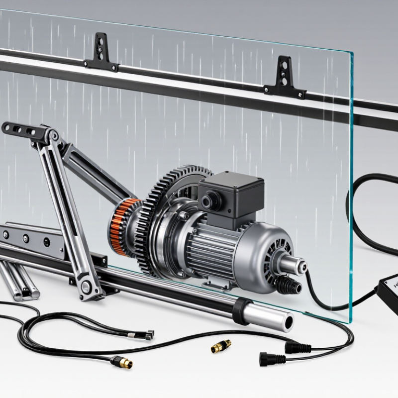
Wiper motor equipment is the powered assembly that moves windshield wiper blades. It converts electrical energy into controlled mechanical motion. A typical unit includes a motor, gearbox, crank arm, linkage, shaft, and control connector. Some systems also include relays, fuses, position sensors, or washer-pump controls. These components usually sit behind the windshield cowl, where moisture and dust can collect. In practical inspections, worn linkage bushings often cause more noise than the motor itself. That detail is easy to miss.
Common types include single-speed, two-speed, intermittent, and electronically controlled motors. Single-speed designs suit basic equipment. Two-speed units provide normal and fast wiping. Intermittent systems pause between wiping cycles. Electronic versions can adjust speed using sensors or control modules. A 12 V system is common in passenger vehicles and compact equipment. A 24 V system is more suitable for larger vehicles and industrial machinery. Voltage must match. Incorrect voltage can overheat windings, damage controls, or produce weak movement.
When the switch sends power, the motor begins rotating. Its gearbox reduces speed and increases torque. The crank converts rotary motion into back-and-forth movement. The linkage then moves the wiper shafts across the glass. Limit contacts help return the blades to their parked position. During diagnosis, measure voltage under load, not only at rest. Check the ground path, fuse, connector, and linkage resistance. Listen for clicking, grinding, or delayed movement. A motor may appear defective when the linkage is actually seized. Technicians should question the first assumption.

Trace the Operating Cycle: From Switch Signal to 40–70 Wipe Strokes per Minute
What Is Wiper Motor Equipment and How Does It Work?
A wiper motor converts electrical energy into controlled blade movement. When the driver selects a speed, the switch sends a low-current signal to a relay or control module. The motor then receives power and begins turning. Inside the housing, a worm gear reduces speed and increases torque. This matters when blades push through rain, dust, or light snow.
A crank arm changes rotary motion into back-and-forth movement. The linkage carries that motion to the wiper arms. In many systems, the motor produces about 40–70 wipe strokes per minute, depending on the selected speed and vehicle design. Intermittent settings add pauses between strokes. A park switch keeps the blades moving until they return to their resting position. The timing is not perfectly silent or instant. Small delays can occur as contacts settle and gears take load.
Tips: Check the blades before testing the motor. Dry glass creates unnecessary resistance. Listen for clicking, grinding, or uneven movement. These sounds may suggest worn gears, loose linkage joints, or weak electrical connections. Measure voltage at the motor connector, not only at the switch. A switch can appear functional while a damaged wire limits current. In workshop checks, technicians should also inspect the ground path. It is easy to overlook.
What Is Wiper Motor Equipment and How Does It Work? — From Switch Signal to 40–70 Wipe Strokes per Minute
Typical operating-cycle data for a 12 V or 24 V automotive windshield-wiper motor assembly. Actual values vary by vehicle design, load, temperature, and control strategy.
| Step | Equipment or Function | Input or Operating Condition | Mechanical or Electrical Action | Typical Result |
|---|---|---|---|---|
| 1 | Wiper control switch | Driver selects intermittent, low, high, or washer mode. | The switch sends a low-voltage command to a relay, body controller, or integrated motor-control circuit. | The requested wipe mode is identified. |
| 2 | Control module or relay | A switch command and vehicle power supply are available. | The circuit applies battery voltage to the motor and may set intermittent timing, speed selection, or washer coordination. | The motor receives a controlled electrical supply, commonly 12 V or 24 V nominal. |
| 3 | Permanent-magnet DC motor | Electrical current flows through the armature windings. | The magnetic field produces torque and rotates the motor shaft. A low-speed and high-speed winding or electronic control can provide different operating speeds. | Rotational speed is commonly in the several-thousand-rpm range before gear reduction. |
| 4 | Worm gear reduction | High-speed, low-torque motor rotation enters the gearbox. | A worm-and-wheel gear set reduces rotational speed and increases torque, allowing the motor to move the arms against glass friction and aerodynamic resistance. | Output speed is reduced to a slow, high-torque oscillating drive. |
| 5 | Crank, link, and pivot assembly | The gearbox output shaft rotates continuously in one direction. | A crank and linkage convert rotary motion into back-and-forth angular motion at the wiper-arm pivots. | The blades sweep across the windshield rather than rotating continuously. |
| 6 | Wiper arm and blade | Oscillating pivot motion is transferred through the linkage. | The spring-loaded arm presses the blade against the glass while the blade’s flexible rubber element conforms to the windshield surface. | Water, snow, and road spray are displaced from the swept area. |
| 7 | Park switch or position sensor | The driver switches the wipers off while the blades are away from the park position. | A normally closed park circuit keeps the motor powered until the linkage reaches its designated rest position, then opens or changes state. | The blades return to the lower windshield area before stopping. |
| 8 | Intermittent timing control | The intermittent mode is selected; delay settings commonly range from a few seconds to approximately 20 seconds. | The control circuit periodically energizes the motor and uses the park signal to end each wipe cycle. | One complete wipe occurs at each programmed interval. |
| 9 | Low-speed operation | Continuous low-speed mode is selected. | The low-speed motor circuit or controller maintains a steady oscillation suitable for moderate rainfall. | Approximately 40–55 wipe strokes per minute is a typical operating range. |
| 10 | High-speed operation | Continuous high-speed mode is selected. | The high-speed winding or electronic drive increases motor speed while the gearbox and linkage continue to provide torque and oscillation. | Approximately 55–70 wipe strokes per minute is a typical operating range. |
| 11 | Electrical protection | The blade or linkage encounters excessive resistance, ice, or an obstruction. | A fuse, circuit breaker, current limiter, or controller protection strategy interrupts or limits current to reduce motor and wiring damage. | The system is protected from sustained overcurrent and overheating. |
| 12 | Complete wipe cycle | The linkage travels from the park position through the sweep and returns to park. | The motor, gearbox, linkage, arm, blade, and park circuit operate as one coordinated mechanical and electrical sequence. | One full wipe stroke is completed, with the system ready for the next command. |
Measurement note: A wipe stroke is commonly counted as one complete blade movement across the windshield and back to the starting side. Stroke-rate figures are representative automotive ranges, not universal specifications.
Examine Motor Output: 30–60 W Power, Torque, Speed, and Self-Parking
A wiper motor converts electrical energy into controlled rotary motion. In many passenger vehicles, its power rating falls between 30 and 60 watts. That figure describes electrical input, not always useful mechanical output. Real performance also depends on load, voltage, gearing, and linkage friction.
Torque moves the wiper arms across wet or heavy glass. The reduction gearbox increases torque while reducing motor speed. Typical arm movement may reach roughly 30 to 60 cycles per minute, depending on the selected setting. Higher speed does not automatically mean better cleaning. Excessive speed can increase vibration, noise, and blade wear. During testing, I have found that dry glass creates misleading results. Water changes the resistance noticeably. A weak motor may still appear acceptable under light conditions.
The self-parking system returns the blades to their lower resting position after the switch is turned off. A cam and contact arrangement keeps power connected until the correct position is reached. Then, the circuit opens. This small feature prevents blades from stopping across the driver’s view. It can also reveal worn contacts when parking becomes inconsistent.
Tips: Measure voltage at the motor, not only at the battery. Inspect the linkage for stiffness before replacing the motor. Compare current draw with the service specification. A stalled motor may draw excessive current and overheat quickly. Leave room for uncertainty; temperature and friction can change the readings.
Assess Durability Through IP Ratings, ISO 16750 Tests, and Duty Cycles
What Is Wiper Motor Equipment and How Does It Work?
A wiper motor converts electrical energy into controlled rotary motion. A linkage then turns that motion into blade movement across the windshield. Durability depends on more than torque. Water, dust, vibration, temperature, and repeated starts can weaken seals and gears.
IP ratings provide the first checkpoint. Under IEC 60529, IP6K7-rated protection means complete dust resistance and temporary immersion protection. However, IP ratings do not measure vibration or long-term wear. For road vehicles, ISO 16750 testing adds realistic stress. ISO 16750-3 evaluates mechanical loads, while ISO 16750-4 examines temperature and humidity exposure. Test conditions may include rapid temperature changes from below -40°C to above 85°C. That shift can expose brittle plastics, swollen seals, and loose terminals.
Duty-cycle testing reveals another failure path. A motor may run for 30 seconds, stop briefly, and repeat thousands of times. Current draw should remain stable during each cycle. A rising current often signals bearing friction or linkage misalignment. Laboratory reports from the automotive reliability sector commonly separate electrical failures from mechanical failures, because both appear differently in endurance data. Still, a pass result is not permanent proof. Real vehicles face frozen blades, uneven glass, and contaminated washer fluid. These details are easy to underestimate. A stronger evaluation combines IP testing, ISO 16750 sequences, thermal measurement, and teardown inspection after cycling.
Diagnose Common Failures Using Voltage, Current, and Linkage Checks
What Is Wiper Motor Equipment and How Does It Work?
Diagnose Common Failures Using Voltage, Current, and Linkage Checks
A wiper motor converts electrical energy to the arm movement that clears rain from glass. Its control circuit usually includes a fuse, switch, wiring, motor, and linkage. When the switch is selected, voltage reaches the motor. Internal contacts may also return the blades to their parked position.
Start with a visual check. Look for loose connectors, damaged insulation, or a blown fuse. Measure voltage at the motor connector with the wiper switch activated. A healthy supply should remain close to battery voltage under load. Check the ground side too. Excessive voltage drop suggests corrosion, a weak connection, or a damaged ground wire. Do not trust voltage alone. A circuit can show normal voltage without delivering enough current. Use a current clamp when possible, or connect an ammeter correctly in series. Never place an ammeter directly across the battery.
Tips: Disconnect power before testing the linkage. Move the wiper arms by hand and feel for stiff pivots, bent rods, or a jammed mechanism. High current often indicates mechanical resistance. Low current with proper voltage can indicate worn motor brushes or an open internal circuit. A quiet motor is not always healthy. I have seen motors spin freely while the linkage remained seized. That diagnosis was incomplete. Recheck the mechanism under realistic load, and remember that an intermittent fault may disappear during testing.
Article Source:
Get in touch with us,
We will contact you shortly!
What is the difference between Unline(Non-Epoxy Coated) or Lining(Epoxy Coated) Metal Drum?

Unline drums with internally bare metal surface is more susceptible to corrosion and rust while Lining drums are internally coated with Phenolic Epoxy Coating to provide a non-reactive barrier between the drum surface and your product, less risk of contamination. Note: Our Unline drums are coated with an anti-rust agent after washing to reduce risk of rust.
What are Unline(Non-Epoxy Coated) and Lining(Epoxy Coated) drums compatible with?

In Singapore, Recon Unline Drums are usually more costly than Recon Lining Drums. Hence, we recommend Recon Unline Drums to fill aromatics like Thinner, Xylene, Toulene& other solvents like Hexane, BA, CA, EA, MC, White spirit, etc.
We recommend the lower-priced Recon Lining Drums to fill hydrocarbons like IPA, Methanol, Ethanoland oil-based products like diesel, petrol, lubricants, engine, hydraulic, base, transmission fluid, additives, waste oil, etc.;
What is the difference between Grade A and Grade B Metal Drum ?

Grading of used drums are usually based on physical conditions like rustiness, deformities and residual contents. Grade A drums are totally free from internal rust, serious dents and are easy to clean. Grade B drums have different degrees of rust internally and aesthetically inferior compared to Grade A drums.
What content is suitable to fill in a Recon Grade A or Grade B Drum?

Recon Grade A drum is suitable to fill more costly virgin grade products while Recon Grade B drum is more suitable for recycled or waste products.
What is the difference between Open Top and Close Top Drums and their usage?

Closed top drums are for water and other liquid products. Open Top drums can be used for liquid too but are primarily for more viscous products. The Open Top (or open head with a lid) allows you to get in and out of the drum with your product easier.
What type of content are Metal or Plastic Drums suitable for?

Metal drums offer additional protection when dealing with potentially flammable substances. They provide superior fire resistance, impact protection, and longevity for storing class 1, 2, and 3 volatile chemicals.
Plastic HDPE Drums are suitable for corrosive chemicals like acids, alkaline and also water-based products.
Will there be any contamination in the reconditioned metal, plastic drums or IBC tanks?

All our reconditioned containers (metal/plastic drums, carboys, IBC tanks) are washed thoroughly with specially formulated cleaning agent, rinsed with clean water, dried, and tested for possible leakages during the recondition process. Stringent quality inspection is being conducted 100% on every reconditioned product before they are qualified for sale & delivery.
What is the drum gauge(thickness) and weight for reconditioned metal drums?

Reconditioned metal drums gauge can be 0.9mm to 1.0mm all round. Their weight can vary from 16 to 18kg.
Do you sell New Packaging Products too?

Yes, we are also a distributor for new pallets, metal drums, plastic drums, carboys, IBCs and stainless-steel tanks.
What additional services do you provide apart from selling reconditioned and new containers.?

We are an NEA licensed toxic industrial waste collector, who can collect and dispose of used toxic waste containers in Singapore.
Do you offer labelling and silkscreen on the containers ?

We can provide labelling and silk-screening on the containers.
Are you able to ship overseas ?

Yes, we can arrange export our products to any country in the world.
Leading the Way
to Carbon Neutrality